Aircraft Flight Instruments
...The leader in aircraft engine data management systems.
 EDM 790 is truly a top-of-the-line Aircraft engine data manager. It is without doubt, the best EDM system that money can buy and provides the best return for your money.
With a price tag a tad under ten grand, the EDM 790 is designed for 4 and 6-cylinder aircraft engines and accessories include the transducers. Billed as the most advanced twin piston engine-monitoring device in the market, is not the only feather in its cap; the EDM 790 has been TSO’d for quality and is as good as having a Flight Engineer and Maintenance engineer onboard; one who never nods off or losses concentration during a flight – not even for a second. The EDM 790 watches over 29 critical parameters: The EDM 790 is designed to watch over 29 critical parameters of the aircraft engine and to sample the data 4 times a second. Nothing even comes close to being as good. Moreover, the FAA has tested the EDM 790 and confirms that the device has a linearized thermocouple accuracy of 0.1 percent or 2 F°. When the testing agency certifies as to the awesomeness of the EDM 790, need we look further? The EDM 790 never loses concentration: It’s a little digital machine that starts work the moment the aircraft engines are fired up. The EDM 790 picks up data for 29 critical parameters, displays the readout on the screen and at the same time, looks for anomalies by comparing the figures with pre-stored data. Any variance is instantly brought to the notice of the pilots by displaying the digits in bright red colour and also flashing a hard-to-miss warning light. Linearized thermocouple accuracy: Search as much as you like but you would be hard-pressed to find another instrument that will match the EDM 790 for accuracy. Two- button simplicity: The EDM 790 faceplate sports two buttons and that is all it takes to programme it. No complicated pre-set required. Also, the pilot can accomplish leaning easily and automatically using the LeanFind™ procedure. Additionally, the JPI EDM 790 offers substantially more diagnostic information for the crew. Here are a few advantages of the EDM 790: 1. Easy-to-use, easy-to-learn 2-button programming. 2. Artificial Intelligence assisted diagnostics. If any errors are detected, the specific code is displayed along with blinking warning LED. 3. Alphanumeric scanning display of 29 functions or channels. 4. Keeps a watchful eye on 29 engine parameters including the Alternator Voltage, EGT Differential, Fuel Flow and Shock Cooling. 5. EGT Bar Graphs are displayed as variable scales. 6. It’s amazing PeakFind™ and the paired probes, automatically captures the EGT Probe or TIT peak value. Also, the LeanFind™ Mode identifies the first and last cylinder to peak. 7. Downloading engine data is easily accomplished with the Data Port. 8. Cooling rate and shock cooling checked on each and every cylinder. 9. The EDM 790 with fuel flow monitor is the only such device to receive FAA approval. 10. Awesome temperature captures accuracy of ONE degree (even for EGT). 11. Comes paired with ‘grounded’ fast response Probes & Sensors. 12. TSO Certificate for reliability and quality. Also, STC and FAA approved for accurate Fuel Flow data. 13. Three-year warranty. For more information, please visit: https://www.jpinstruments.com/shop/edm-790/
0 Comments
 The compact Engine Data Manager 350 manufactured by California based, J.P. Instruments is a small foot-print digital device that keeps track of several key functions of your aircraft engine.
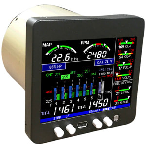
Smaller than the average cell phone, the EDM 350 requires just 3.25 square inches of space amongst your instrument panels. Despite its size, the EDM 350 engine data manager, is a powerful little gadget that is armed with the ability to analyse data from 24 different streams. It’s your extra pair of eyes that keeps watch over the engine while you enjoy the flying. The EDM 350 is suited for any 4 or 6 -cylinder aircraft with the basic kits (for the 4-cylinder aircraft) starting at just $798 and the 6-cylinder one priced at $988. An extra paid of intelligent eyes for under $1,000 is definitely a bargain. Any aircraft maintenance technician will tell you that fitting the EDM 350 in the 4 or 6-cylinder aircraft is a piece of cake! All you need to do is, first attach the probes and next attach them and the wires to the EDM 350 instrument. Finally, ‘plug-in’ the instrument into the 3.5-square inch space provided for it and you’re done. What could be easier? Now let’s see how the EDM 350 works: The EDM 350 is packed with powerful electronics that can do complex comparisons in nanoseconds and decide whether a particular set of figures is ‘high‘, ‘low’ or ‘normal’. It does this for 24 different engine parameters and all at the same time. No human can match this ability. When the pilot switches on the aircraft engine, 24 highly sensitive sensors attached to different parts of the aircraft engine, begin transmitting data to the waiting EDM 350 which in turn interprets the data, displays it on the LCD screen and also intelligently decides whether everything is normal or whether there is a problem. Abnormal figures are displayed in red. The EDM 350 keeps watch over these engine parameters: 1. EGT - Exhaust gas temp. 2. Cylinder head temp. 3. ROP/LOP - Lean finder. 4. VDC - Voltage display. 5. DIFF - Engine health. 6. CLD - Shock cooling on all cylinders. 7. Convenient USB data port for data download. 8. Memory for recording 600 hours of data. 9. Custom software that includes Google Earth location. 10. RPM - Prop rotation speed. 11. MAP - Engine Manifold pressure. 12. F.P. - Fuel pressure. 13. O.T. - Engine oil temp. 14. OAT - Outside air temp. 15. O.P. - Engine oil pressure. 16. TIT Probe - Turbine inlet temp. 17. CRB Probes - Carburettor temp. 18. L-R-Main - Fuel quantity in all tanks. 19. CDT - Compressor discharge temp. 20. V-2 - Second volts readout. 21. AMP - Battery load output in amps. 22. Amp-2 - Second load readout in Amps. 23. Percentage HP - With FF, OAT and RPM. 24. FF - Fuel flow includes: • REQ - Fuel required to way point / destination. • GPH - Gallons per hour. • H:M - Endurance in hours and minutes. • USD - Fuel used. • MPG - Miles per gallon For more information on EDM 350 Aircraft Engine Data Management by J.P. Instruments, please visit: https://www.jpinstruments.com/shop/edm-350/ 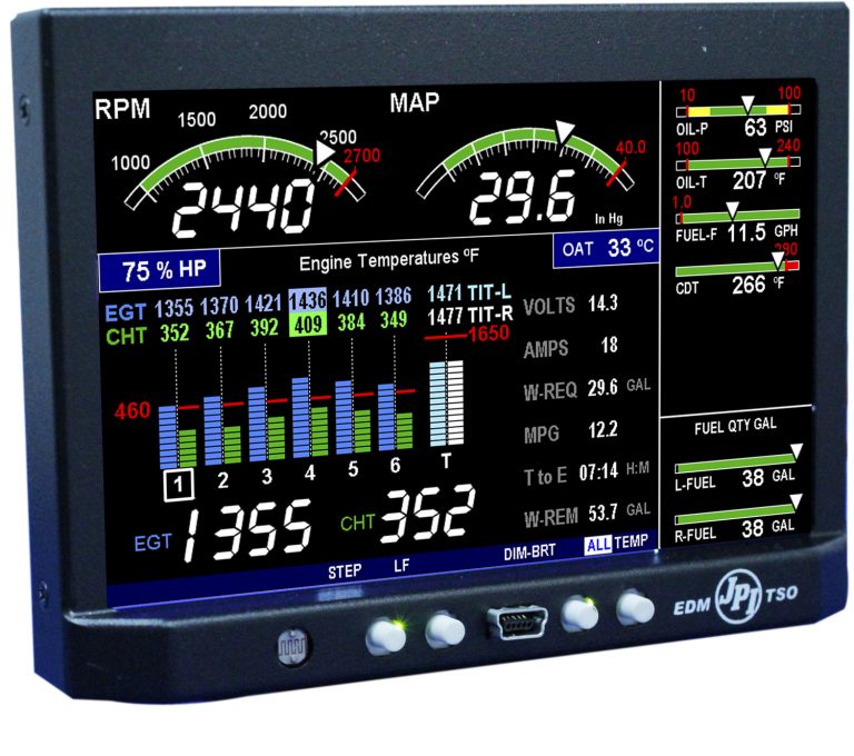 Data display on the EDM 900:
 There are analog dials, there are digital scanners and then there are classic scanners – each better than the previous. All these dials and scanners are used in modern aircraft to provide engine related information to the pilot(s).
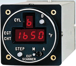
Let’s say as a pilot flying an aircraft, you wanted to know the Exhaust Gas Temperature (EGT). You could do it the old-fashioned way by installing an analog dial EGT gauge or, you can do it the modern way by installing a digital scanner. A typical scanner (depending on its sophistication), is paired with one or more sensors / probes e.g. EGT and CHT probes. Each of these sensors or probes in turn, is plugged into different parts of the aircraft engine. These sensors (or probes) send back data to the scanner. The scanner displays the data on a small screen. Also, a scanner (again depending on its level of sophistication), may also have buttons on the face-plate to facilitate menu selection. Classic scanners as manufactured by J.P. Instruments of U.S.A, represent State-of-the-art technology and most of their models are capable of audio-visual indicators. The alarm is triggered when incoming data is at variance with factory set parameters - for example (depending on the scanner), low RPM or low fuel or high temperature and so forth. Generally, most pilots/aircraft owners tend to buy a classic scanner when they need to replace an existing analog gauge. Instead of replacing it with another analog gauge, they upgrade to a classic scanner. The J.P. Instrument manufactured Classic Scanner is a small convenient package with an even more convenient price tag. It was first introduced 20 years back and has since been continuously upgraded. Over the years it has proved its reliance, accuracy and durability. Economical to buy and easy to install and use, the Classic scanner has large red LED display that makes it very easy to read in all weather and light conditions. Flawlessly accurate, the Classic Scanner is paired with JPI’s famous super accurate fast-response Probes & Sensors. The Scanners are FAA TSO approved (Aerospace Standard AS 8005 and RTCA Documentation DO160A) and comes with a one-year limited warranty. The J.P.I. Classic Scanner comes equipped with a ‘dimming’ switch located on the top of the scanner. Each press alternates between bright and dim. The EGT – CHT classic scanner has a hole on the bottom of the scanner. The pilot can use a screwdriver to easily increase the number channels scanned (up to 8) in an Aircraft Engine Monitor. Different models have functionality and features depending on the speciality of that particular scanner. For example, in the case of above mentioned EGT-CHT classic scanner, the pilot can alter the indexing rate. This model also comes equipped with a visual alarm that is triggered at 450°F (for CHT) and 1650°F (for TIT). Knowing that the scanner will alert the pilot in case of any abnormality, the pilot needs no longer watch the EGT – CHT and instead, can enjoy the flying. For more information on Classic Scanners, please visit: https://www.jpinstruments.com/shop/classic-scanner/ 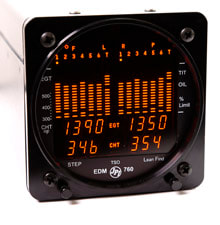 If you have purchased or are thinking of purchasing the J.P.I. Engine Data Manager EDM 760 for your aircraft and want to know more about its features and operation, you’ve come to the right place.
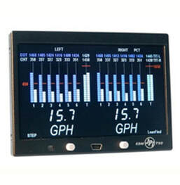
To begin with, the 760 series engine data management is one of the finest engine monitoring instruments available for piston engine aircraft. The J.P.I. EDM 760 system for aircraft is as good as a personal flight engineer and once installed, will keep working in the background watching over the aircraft engine(s) while you concentrate and enjoy flying the aircraft. The EDM 760 System and its advantage to your aircraft: The EDM 760 connects to the aircraft engine via multiple sensors. These sensors pickup up the engine data and transmit it via wires to the EDM unit. The EDM unit in turn, displays the data as numbers or coloured graphics on the unit’s LCD screen. Furthermore, it compares the data with pre-fed upper and/or lower limits and will alert the pilots via audio visual indicators if data from any part of the aircraft engine falls below or exceeds the expected range. The pilot can therefore enjoy the flying rather than having to constantly scan a bunch of analog dials. Additionally, the EDM 760 system will monitor the aircraft engine three times a second. As a human, you may miss it and not notice a problem beginning to happen, but the EDM 760 will not miss any discrepancies in engine performance. Here’s how the J.P.I. EDM 760 works: First, it collects data and displays it for the pilot in a useful way. For example, as a pilot, you can monitor the engine temperatures and voltages, adjust the fuel air mixture and diagnose engine malfunctions. The EDM 760 consists of two clusters of bar graphs one for the left Single Engine Monitors and one for the right central. Each of these will provide the exhaust gas temperature (EGT) bar graph and the height of each bar in the graph represents oil temperature or turbine Inlet temperature (TIT), depending on the options installed in your aircraft. These bar graphs enable the pilot to see subtle changes in temperatures being displayed. The EDM 760 has two buttons on the front panel both of which; control all functions of the EDM 760. On the left side is the step button and on the right is the lean find button. One minute after the EDM 760 is turned on it will automatically index through all parameters. Tapping the step button will stop the automatic scan and always take you into the manual indexing mode through which, the pilot can observe each parameter value for as long as they want. To begin or resume automatic indexing they only need to tap lean find and then tap step to switch between the percentage view and the normalized view. If the EDM 760 and EDM 900 that you’ve purchased has the fuel option installed, then the unit uses the known quantity of fuel aboard the aircraft to keep track of all fuel consumed fuel remaining in the tanks. It also calculates the endurance on a total aircraft basis and so forth. For more information, please visit: https://www.jpinstruments.com/shop/edm-760/ 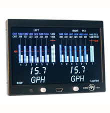 The EDM 790 manufactured by J.P. Instruments, U.S.A. is perhaps the best Engine Data Management system that money can buy for under US 10K for 4 or 6-cylinder aircraft engine – and this also includes the transducers.
If you are looking for the best deal for a twin piston engine-monitoring instrument in the market, look no further than the awesome EDM 790. It has been TSO’d for quality and is considered as the Flight Engineer and Maintenance Manager of your aircraft. Covers all 29 critical parameters Your twin engine aircraft has 29 critical parameters that ideally require constant monitoring – and you know how tough it can be. The EDM 790 does it for you! Equipped with the latest hardware and software technology, the EDM 790 will monitor all 29 critical parameters of your aircraft engine and it does this 4 times a second! Moreover, it has a linearized thermocouple accuracy that is better than 0.1 percent or 2 F° and this has been verified and tested by the FAA. The EDM 790 never sleeps From the moment the pilot switches on the aircraft engines, the EDM 790 via the sensors will keep an eye for you on all the critical parts of your aircraft engine. Each and every one of them is automatically checked four times every second. No matter which page of data you might currently be looking at, the EDM 790 continues to work in the background running checks on all 29 critical parameters. EDM 790 accuracy has been verified and tested by the FAA. The EDM 790’s linearized thermocouple accuracy is simply the best in the market - there is nothing in the aviation market that compares to J.P.I EDM 790’s linearized accuracy. The EDM 790 is simplicity personified There are two buttons on the faceplate and that is all it takes to programme the EDM 790. The pilot can also access all the functions via these same two buttons. Leaning is accomplished using the patented LeanFind™ procedure. Also, with the new EDM 790, the ground crew has substantially more diagnostic information available. Features and Specifications of EDM 790 include: 1.Hardware and software assisted aircraft engine diagnostics covering the entire aircraft. Error detection includes display of specific error code. 2.Easy-to-use front panel 2-button programming. 3.Twenty-nine parameters including EGT Differential, Alternator Voltage, Fuel Flow and Shock Cooling are checked 4 times a second. 4.Includes variable scaling of EGT Bar Graph. 5.The patented LeanFind™ Mode automatically identifies the first and last cylinder to peak. 6.The PeakFind™ with quick responding probes automatically captures the EGT or TIT peak value. 7.Data Port for easy downloading of data to any compatible external gadget. 8.The EDM 790 includes a complete fuel flow system and is the only FAA approved graphic Aircraft Engine Monitors to do so. 9.Accuracy in temperature detection is ONE degree (even for EGT). 10.The EDM 790 is paired with JPI’s “grounded” fast response probes. 11.Each and every cylinder is tested for cooling rate and shock cooling. 12.The EDM 790 also features a “Normalize Mode”. This helps in trend monitoring and for accuracy, bars are in 10o increments. 13.This EDM features alpha-numeric scanning display of 29 critical parameters. 14.EDM 790 and EDM 930 has been TSO’d for reliability and quality with FAA, and includes STC approved Fuel Flow. 15.Comes with a 3-year warranty. For more information, please visit: https://www.jpinstruments.com/shop/edm-790/ 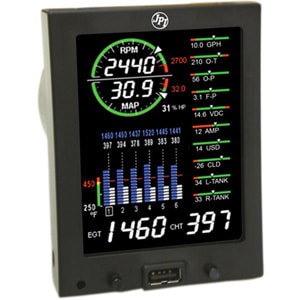 For technicians about to install the JPI EDM 740 in an aircraft, this article is for you. It covers all the general points to installing the JPI EDM 740.
To start with, only FAA certified aircraft mechanic should attempt to install the EDM 740 in aircraft. General Installation Instructions: 1.The EDM 740 (as do all EDM’s), are equipped with a delicate LCD display module. To prevent any damage to it, it is imperative that the mounting screws not penetrate the instrument by more than 0.12 inches. Ideally, use the steel template supplied with the installation kit. 2.The aircraft on which the EDM 740 is to be installed, should have necessary FAA approvals. 3.Special attention and care should be taken while crimping the wires. It is recommended that the technician fold back the wire double before crimping terminals. 4.Avoid aluminium fittings for planes equipped with FXT-201 or FXT-231 fuel flow transducer. 5.Before you begin, note down the K-factor (see side of the fuel flow transducer) 6.Map the holes and make sure there is nothing behind the panel that is likely to get damaged during the drilling process. 7.Provide service loops for all wires near the panel as well as near the engine (including Thermocouple wire) Service loops near the aircraft engine are required probes can be swapped for troubleshooting purposes. 8.Tie/keep wires away from heat sources. 9.Where soldering is required, use zinc chloride flux such as Nokorode brand. 10.Polarity of wires is vital and EDM 740 must be grounded at the engine, not at the avionics ground. 11.If the aircraft has a spark plug gasket probe, the CHT reading on that cylinder will be somewhat higher than cylinders with bayonet probes. Optionally, you could opt for an adapter probe (bayonet or screw-in) so that the factory CHT Probes and the JPI probe to be placed in the same bayonet location. 12.Wires from the probes and sensors should be routed through the firewall using fireproof rubber grommets and flame retarding silicone. Rather than drilling new holes, make use of existing holes. 13.Keep sufficient slack (but ensure the wires do not touch the engine surface). Secure the probe leads roughly 8 to 12 from the probe. 14.The JPI RPM Sensor kit comes with a 3-pin connector – please, only use this connector. 15.Make sure the wiring does not obstruct the controls or anything else under the panel. 16.Ensure the probe wires are not tied in with alternator, ignition or twin-engine cabin heater ignition wires as there is possibility of interference with temperature readings. 17.While power and ground wires are normal copper, the temperature probe wiring harness is made of Chromel-Alumel alloy wire (yellow). Do not substitute it or extend with normal copper wire – these are not compatible. Leads may be spliced only with additional Chromel-Alumel wire using copper butt splices. 18.On completion of the installation process, all wires should be secured using ties and carefully checked for rubbing, interference or chaffing with flight control cables or other moving parts. For more information on J.P. Instrument’s EDM-740, please visit: https://www.jpinstruments.com/shop/edm-740-experimental-only-3/  Combustion whether in aircraft or cars or anything that has an engine, not only relies on accurate mixture of air with fuel before ignition, it also requires the air and fuel to be at optimal temperature - this ensures instant and clean combustion.
Aircraft typically fly at altitudes where the air is very cold. This cold, dense and often freezing air impedes combustion and may even need to be pre-heated before mixing with fuel. So how does the aircraft know if the air is at the correct temperature or not? This is where the Intake Air Temperature (IAT) sensor comes into play. An automobile engineer’s solution to the cold air problem would be to increase the fuel in the fuel-air mixture. Cold air being dense, the extra fuel in the mixture corrects the fuel-to-air ratio and ensures proper combustion. The increased fuel consumption is not a problem as a land-based vehicle can stop at the nearest fuel station and fill up – this however, is not an option for aircrafts. The aircraft therefore, is designed to pre-heat cold air so it is ‘combustion-friendly’. Whether to heat or not, is triggered by the onboard engine controller that is fed with data from the IAT probe. The IAT probe directly feeds air temp. data into the air temp indicator / onboard controller. Based on the air temp data received from the IAT probe, the engine controller dynamically alters the air-to-fuel ratio by changing the timing of the injector pulses. When installing the Intake Air Temperature (IAT) probe, only the tip of the probe is exposed to external air entering the aircraft engine. The IAT probe itself is mounted just inside the air intake manifold of the Aircraft Engine Monitor. How the IAT probe works: Technically, the IAT probe is a thermistor. This means its electrical resistance is directly proportional to the changes in the air temperature i.e. the output voltage from the IAT probe varies depending on the air temperature. The output voltage for your aircraft’s IAT probe is usually mentioned in your aircraft service manual (or the leaflet that came with the IAT probe -if you’ve purchased a new one). On ground, the pilot needs to eyeball the IAT probe to ensure it is not coated with sooth, oil or bird feathers as these could cause the IAT probe to malfunction. A malfunctioning Air Temperature Probe will in turn the on-board engine computer miscalculating the air-to-fuel mixture. More information on IAT probes for aircraft can be found here: https://www.jpinstruments.com/product-category/probes-sensors/ 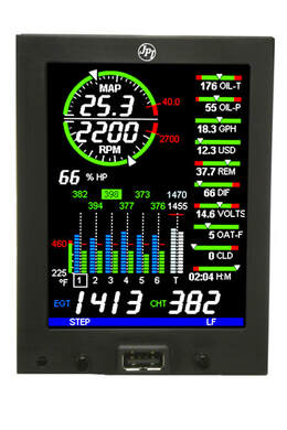 Even the Wright brothers plane had a couple of dials near their seat in the plane. If nothing else, they at least had to know how much fuel they had in the fuel tanks.
Without the presence of a working dial or two, as a pilot, you wouldn’t have the foggiest idea on what was happening in the engine compartment – let alone know where they were going. Today, thanks to aircraft engine monitors, the pilot is often aware of a major life-threatening aircraft engine malfunction before it even happens. Are the cylinders over-heating? Is there a fuel line block? Is the magneto malfunctioning causing the voltage to fluctuate or drop? And so on and so forth. The aircraft engine monitors are similar in function to the monitors we see in a hospital – monitors that monitor the vital life signs of a patient. A single glance at the monitors and the doctor becomes fully aware of the patient’s life status. Ditto the aircraft pilot. Aircraft engine monitors and gauges supply the pilot(s) with visual data regarding the health of the aircraft engine and its current performance in real-time. Combine these with GPS and your pilots not only know the state of the engine, they also know their exact current geographic location. Any engine has certain manufacture determined safety parameters within which it has to operate. Any deviation is a malfunction that could lead to a catastrophic failure. These days, thanks to IC technology and AI software, aircraft engine monitors not only provide data, they actually watch over the aircraft engine and provide a visual or audio-visual warning to the pilots if and when any engine parameter is not within operating limits. To further improve the functionality of the aircraft engine monitors, manufacturers such as J.P. Instruments amongst others, have gone a step ahead and inserted memory cards within the engine monitors. The memory card enables the maintenance crews to download engine data via convenient USB / serial ports. This data can not only be analysed by the maintenance crew, over time, they help keep a record of the engine performance. Every part of the aircraft engine is vital which explains why some of the engine monitors and engine Digital Gauges include engine pressure and temperature gauges, RPM counter, fuel flow and fuel level gauges (one set per engine), air intake temperature and so forth. Every part of the aircraft engine is monitored which also explains why the aircraft cockpit used to have so many dials and knobs crammed into every nook and corner of the cockpit. Today however, thanks to Engine Monitor the aircraft cockpit looks more like a gamming room with just a few futuristic looking LCD/LED screens and a dozen dials. These futuristic looking screens are called ‘EDMs’ - Engine Data Managers and they have replaced most of the monitors and Airplane Gauges of earlier times. JPI is a leading manufacturer of after-market gauges, EDM and sensors used in aircraft: https://www.jpinstruments.com 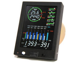 Either you are planning to upgrade from an older EDM to EDM 730 or are planning on replacing some analog dials with the EDM 730 but in either case, your choice of EDM 730 could not have been better.
The Aircraft Engine Data Management 730 is an awesome piece of technology that offers clear, full-colour high-contrast graphics. It is easily installed (vertical or horizontal) and is considered as the most advanced and accurate piston engine-monitoring and advisory instrument on the market. It has been TSO’d for quality. The Aircraft Engine Data Management 730 is one of the easiest to programme and all programming is done from the front panel. Here is an abridged list of its features and specifications: 1. Easy to install. 2. Clear, Full-Colour Graphics. 3. Easy to programme. 4. Annunciation of exceedances. 5. Easy-to-read data display. 6. Fully tested and approved. 7. Displays more information per page. Package Form Factor: 1. Four mounting options. 2. Requires only 3-1/8" space. 3. Just 65mm depth. 4. Easy to adjust location. 5. Data download via USB port. 6. Easily upgradable from 700 series JPI EDM’s. 7. Pilot programmable parameters. 8. Just press button for Rich of peak or lean of peak operation. 9. Horsepower display in percentage. 10. Graphically display of RPM and manifold pressure. 11. Fuel management can be linked to GPS. 12. Computerized fuel-flow system. 13. EDM 730 scanner function. 14. Ideal for 4/6/7/8/9-cylinder engines. 15. Display in portrait or landscape. 16. Turbocharged engines. Optional: 1. JPI Carb Temp Option 10-27103 2. JPI Oil Temp Option 10-27100 3. JPI RPM Sensor Option 10-01720 4. JPI Oil Pressure Option 10-04075 5. JPI Manifold Pressure 10-04512 6. JPI OAT Option 10-27095 7. JPI TIT Option 10-27090 More information here: https://www.jpinstruments.com/shop/edm-730-2/ |
AuthorJ.P.Instruments was founded in 1986 in Huntington Beach, California, USA. Its founder, Joseph Polizzotto, is now the current CEO. Archives
May 2019
Categories
|

 RSS Feed
