Aircraft Flight Instruments
...The leader in aircraft engine data management systems.
 Just so there is no confusion, the RPM sensors we refer to, are the ones used for measuring the RPM of the Bendix Magneto or the Slick Magnetos in aircraft. Some aircraft use Dual Magnetos but Bendix Magnetos and the Slick Magnetos are more widely used.
One of the main reasons the Bendix Magnetos are popular is because they are easily overhauled and for any aircraft; this is a winning feature as it saves time and money. Amongst the most prominent companies that manufacturer highly accurate aircraft RPM sensors, is J.P. Instrument – they manufacture sensors for Bendix Magnetos as well as Slick Magnetos. Just in case you are unaware, spark plugs in any aircraft engine are powered by the magnetos – these act like mini power generators and even have a built-in transformer, breaker switch and a distributor – all used to provide high voltage to the spark plugs. In a standard magneto (or dynamo), there are rotating magnets and electrical coils inside the housing. As the magnets rotate, the electrical coils generate power. The rotation has to be kept within pre-prescribed limits as the output voltage has to be constant and uniform. Any variations will lead to instant problems as the spark plugs will either not fire at all or go out of sync and the engines will misfire. The pilots therefore need to be aware the Bendix magneto is working properly and this is enabled via the RPM Sensor - a small-ish device that is attached to the magneto and provides the RPM readout in the cockpit. Installation or replacing your RPM Sensor for Bendix Magneto is easy Once the housing is open, just remove the vent plug from the port on the magneto (the vent plug covers the portion of the magneto that contains the rotating magnet). Remove the existing Aircraft Sensor Systems if any and insert the new RPM sensor (Dual, Bendix and Slick Magnetos have different RPM sensors). Gently route the wiring bundle towards the firewall – while doing so, make sure you do not attach the bundle directly to the ignition, harness or magneto p-leads. Maintain a bit of slack in wiring so nothing gets unplugged during flight. Technical data to remember while installing your new RPM sensor: • Align the sensor with the correct vent plug of your Bendix magneto - when the position is correct, you should be able to see the rotating magnet through the vent – not the ‘gear’. • The RPM for a 4-cylinder engine would be 3600 rpm, 2400 for a 6-cylinder engine, 1800 for 8-cylinder and 1600 RPM for a 9-cylinder engine. If using a dual mag, a 4-cylinder engine should have rpm of 1800 while that of a 6-cylinder engine should read 2400. • The red wire of the Aircraft Sensors should be connected to the ‘+ve’ supply rated at 5 volts. When replacing your old RPM Sensor, make sure you buy a good quality RPM standard sensor – you really don’t want false or inaccurate RPM reading. More information on JPI manufactured RPM standard sensors here: https://www.jpinstruments.com/shop/rpm-sensor-for-bendix-mag/
0 Comments
 For the uninitiated, an oil temperature probe is required keep a check on the oil temperature. The oil temperature is vital to maintain its viscosity. A low temperature will make the oil useless whereas a higher than normal temperature will risk a whole lot more than just engine damage.
An oil temperature sensor is inserted into the aircraft engine (please see latter part of this article on how to install the oil temperature probe), and the wires are connected to the oil temperature indicator or EDM if your aircraft cockpit sports an EDM. If the EDM permits it, the pilot can pre-set an alarm for the oil temperature so an audio-visual alarm sounds if the temperature drops to below a certain level or raises above a certain level (usually 180F or thereabouts). Since oil plays a vital role in any aircraft, the pilots need to ensure the oil temperature probe and gauge are not only in good working condition, they are also accurate. This is done by an expert mechanic who will spot oil temp probe / gauge calibration errors. All such errors need instant attention – either recalibration or a replacement. Once the mechanic completes his task, it is best if the Aircraft Gauge, sensor, and interconnect wiring be calibrated by a qualified technician or agency before flight. This is deemed prudent as even a small 5% or 10% make a huge difference to the engine. The error could result in the pilot take unnecessary measures or not taking any measures. The latter especially could prove fatal. From experience, we can state that even new oil temperature probes need calibration – or at least testing to ensure the reading they provide is accurate. These days however, with the arrival of IC based integrated avionics and LCD displays, engine data is generally more reliable than what they once were just a few years back. J.P.I. manufactured EDM’s allow for the display of several different engine gauges on a small but clear to read LCD screen. Installation of the oil temperature probe in aircraft The Oil Temp Probes in aircraft is installed by removing the pipe plug located on the front of the engine inline with the push rods. This oil galley feeds the valve lifters. Insert the probe supplied with the kit and check for leaks after installation. The probe leads are routed back to the cockpit along with the EGT Probe wires. Attach these to the appropriate gauge or EDM. More information on oil temperature probes can be found here: https://www.jpinstruments.com/shop/oil-temp-probe/ 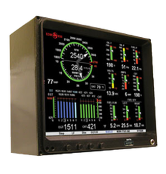 Called by various names including EDM (Engine Data Monitor), ECM (Engine Condition Monitoring) etc. these are essentially aircraft engine monitoring systems. These electronic monitoring cum display units are at heart, a very simple device and this article aims to explain in simple language, how these devices work.
There are two parts to any aircraft engine monitoring system: 1. The EDM / ECM itself and, 2. The probes The probes: If you have ever been inside the ICU of any hospital, you might have notice patients hocked up to a monitoring system. On the patient are attached various sensors all leading to the monitoring unit. The sensor probes in any aircraft work in exactly the same way. These probes have a sensor housed within an appropriate metallic body that enables the mechanic to clamp it onto the aircraft engine. The sensor itself is usually inserted into the engine. The reading is transferred via electrical wires back to the cockpit and is then connected to the aircraft engine monitoring system. Any aircraft – even the single engine ones have numerous probes. In days gone by, each probe used to be connected to its specific dial in the cockpit. The cockpit therefore used to have numerous dials and indicators. These days however, the probe converts the reading into an electrical pulse which is transmitted via electrical wires to the aircraft engine monitoring system. The aircraft engine monitoring system: In absolute simple terms, the aircraft engine monitoring system has three parts to it – display, intelligent data comparison and, data storage. Display: Every EDM Monitors or ECM aims to display the data in a way that helps the pilot(s) to get the gist of what is happening inside the engines in a single glance! The data is presented graphically and in figures. Most EDM’s of today also permit the pilot to choose what is displayed and how. Standard data comparison: Most EDM / ECMs permit the pilot(s) to key in upper and lower limits for every probe. The aircraft engine monitoring system compares the incoming values to the pre-entered upper and lower limits. So, if the EGT (Exhaust Gas Temperature) is approaching or is higher than the upper limit (or lesser than the lower limit), that was keyed in, the aircraft engine monitoring system will trigger an audio-visual signal thereby gaining the pilots attention. Intelligent data comparison and analysis: Aircraft Engine Monitoring Systems can not only accept data from the probes inserted into various parts of the engine, it can also accept inputs from the GPS navigation and compare the navigation output with level of fuel in the tank. It can analyse and deduce whether there is enough fuel to complete the trip and provide this information to the pilots. If the pilot(s) change the destination the Aircraft Engine Monitoring Systems will recompute fuel availability in seconds. Data storage: Aircraft engine monitoring system have built-in memory modules to store data. This stored data can be downloaded for analysis via the USB or other ports located on the aircraft engine monitoring system itself. Visit Here:- https://www.jpinstruments.com/ 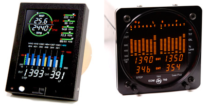 We present a comparison between EDM 730 and EDM 760 – both Engine Data Monitors are manufactured by JP Instruments; World leader in onboard flight instruments and aircraft engine data management systems.
JP Instrument’s aircraft engine data monitors provide the pilots with real time information for aircraft. These systems constantly monitor the health of the aircraft engine and any anomalies are instantly brought to the pilot’s attention via audio-video alarms. This leaves the pilots to concentrate on the flight experience rather than constantly monitoring the engines. This article provides you with relevant information to compare two great engine data monitoring systems manufactured by J.P. Instruments; the EDM 730 and EDM 760. EDM 730 From $1,557.00 to $3,965.00) Features: 1. Easy to install. 2. Clear, Full-Colour Graphics 3. Easy-to-read data display 4. Easy to programme 5. Annunciation of exceedances. 6. More data per page - less page swapping. 7. Fully approved. Package Form Factor: 1. Requires only 3-1/8" space 2. Easy to adjust location. 3. 4 mounting options. 4. Just 65mm depth 5. Easily upgradable from 700 series JPI EDM’s. 6. Data download via USB Download Box. 7. Pilot programmable parameters. 8. Horsepower display in percentage. 9. Just press button for Rich of peak or lean of peak operation. 10. Graphically display of RPM and manifold pressure. 11. Computerized fuel-flow system. 12. Fuel management can be linked to GPS. 13. EDM scanner function. 14. Display in portrait or landscape. 15. Ideal for 4/6/7/8/9-cylinder engines, 16. Turbocharged engines Optional 1. JPI Carb Temp Option 10-27103 2. JPI RPM Option 10-01720 3. JPI Oil Temp Option 10-27100 4. JPI Oil Pressure Option 10-04075 5. JPI OAT Option 10-27095 6. JPI Manifold Pressure 10-04512 7. JPI TIT Option 10-27090 More information here: https://www.jpinstruments.com/shop/edm-730-2/ EDM 760 From $3,675.00 to $8,1000.00) Using the latest microprocessor technology, the EDM will monitor up to twenty-four critical parameters in your engine, four times a second, with a linearized thermocouple accuracy of better than 0.1 percent or 2 F° which has been verified and tested by the FAA and thus TSO’d (Technical Standard Order). The EDM is constantly “red-line” checking all 29 critical parameters (not 16) that are automatically checked FOUR TIMES A SECOND, regardless of current display status. Features: 1. Latest microprocessor technology 2. Monitors 24-critical Aircraft Engine Monitor parameters – 4 times every second. 3. Linearized thermocouple for better accuracy - verified and tested by the FAA. 4. Uses just two buttons for all programming functions of the EDM. 5. Computer Assisted Diagnostics for the entire engine. 6. 29 Alarms, including Shock Cooling, EGT Differential, Fuel flow and Alternator Voltage. 7. Excellent variable scaling of EGT Bar Graph. 8. Patented LeanFind Mode automatically identifies the first and last cylinder to peak and while patented PeakFind system has quick responding probes to automatically capture EGT or TIT peak value. 9. USB Data Port. 10. FAA approved Fuel-flow monitoring system. 11. Alphanumeric scanning display of 29 functions or channels Accessories: 1. EGT Probe PN- M111 2. PC Interface Cable for EDM 700, EDM 800 and EDM 760 3. ALternate USB Download Box 4. CHT Bayonet Probe More information here: https://www.jpinstruments.com/shop/edm-760/ |
AuthorJ.P.Instruments was founded in 1986 in Huntington Beach, California, USA. Its founder, Joseph Polizzotto, is now the current CEO. Archives
May 2019
Categories
|

 RSS Feed
