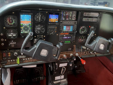
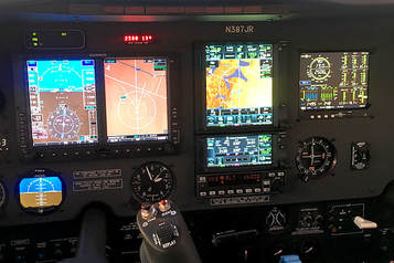
Aircraft Flight Instruments
...The leader in aircraft engine data management systems.
 It is important to check the fuel level before the start of a journey. This is necessary for any means of transportation – cars and aircrafts. This is required in order to avoid stopping and refueling alongside the delays and inconveniences that may result.
There are some devices that can be installed in an aircraft that can accurately determine the fuel level. They are necessary in order to minimize disasters that may result when an aircraft runs low on gas. These devices are called fuel flow indicators. They operate on several basic principles that are all aimed at determining the precise level of fuel in an aircraft. Overview on how fuel flow indicators work A typical fuel flow indicator is composed of several displays for the following items with each item represented as symbols • Fuel used (USD) • Fuel remaining (REM) • Hours and minutes remaining (H.M.) • Fuel required to waypoint and destination (REQ) • Fuel reserve (RES) The function of each of these symbols include Fuel Used (USD) This indicator shows precisely how much fuel was used after the last refueling. As the fuel level increases due to increased usage, the number displayed will increase as well. This indicator can also be programmed to show just how much fuel was used on a multi-fuel stop flight. Fuel Remaining (REM) With fuel indicators, the total fuel remaining in the aircraft can also be calculated. This enables the pilot to have an idea of how much longer the remaining fuel in the aircraft would last and when to refer it. The Fuel Remaining Hours And Minutes Remaining Fuel flow instruments are also programmed to show how long an aircraft can continue on a flight. This value is called the endurance time and it is represented in hours and minutes. The value is calculated based on the current fuel flow rate at a particular time. Variations exist in the value of the endurance time. This variation is shown in different circumstances including • During sea-level climb: Half the actual time is shown on the indicator • During a power reduction descent: More time than is actually available is shown on the indicator Fuel Reserve Based on the destination programmed on the GPS, the Fuel Flow Instruments is able to calculate how much fuel is left in reserve when the aircraft arrives that destination. In summary, Fuel Gauges show the level of fuel in an aircraft to the pilot. This is usually necessary to prevent fatal incidents and in determining the health of an aircraft engine. The fuel flow indicators literally show any malfunctioning so that proper care and repairs can be given. Hence, they are very important pieces that must be installed on any aircraft. Visit Here:- https://www.jpinstruments.com/
0 Comments
 What are Aircraft Instruments?
Aircraft pilots cannot just look out of the window and know where they and what is going on around them. They instead rely on instruments. Instruments essentially concern measurement. Common aircraft measurements include fuel consumption, direction, position, speed, and altitude. Aircraft instruments are basically grouped in two ways: 1) work performance; and, 2) operating principles. Instruments that measure work performance include vertical speed, altimeter, and airspeed. The basic principles of engine operation concern the relationships between the temperature, volume, and pressure of gases. Instruments that measure operating principles, therefore, include those that measure such interactions. What are Atmospheric Aerosols? Aerosols are minuscule, suspended particles in the atmosphere. They drastically influence climate. They impact radiative transfer by absorbing sunlight, by scattering, by altering clouds’ lifetime, amount, and microphysical structure. When they are big enough, we can see them scatter about and absorb sunlight. How Can Aircraft Instruments be used for Characterization of Aerosol Optical Properties? For experts to study atmospheric aerosols’ effect on climate, they need to understand their optical properties. Aircrafts have been productive in characterizing the atmospheric aerosol optical properties. Vertical distributions of aerosol optical properties based on Aircraft Engine Data Management over the Loess Plateau were measured for the first time during a summertime aircraft campaign, 2013 in Shanxi, China. Data from four flights were analyzed. The vertical distributions of aerosol optical properties including aerosol scattering coefficients (ssc), absorption coefficients (sab), Angström exponent (a), single scattering albedo (?), backscattering ratio (ßsc), aerosol mass scattering proficiency (Qsc) and aerosol surface scattering proficiency (Qsc') were obtained. The mean statistical values of ssc were 77.45 Mm- 1 (at 450 nm), 50.72 Mm- 1 (at 550 nm), and 32.02 Mm- 1 (at 700 nm). The mean value of sab was 7.62 Mm- 1 (at 550 nm). The mean values of a, ßsc and ? were 1.93, 0.15, and 0.91, respectively. Aerosol concentration decreased with altitude. Most effective diameters (ED) of aerosols were less than 0.8 µm. The vertical profiles of ssc,, a, ßsc, Qsc and Qsc' showed that the aerosol scattering properties at lower levels contributed the most to the total aerosol radiative forcing. Both a and ßsc had relatively large values, suggesting that most aerosols in the observational region were small particles. The mean values of ssc, a, ßsc, Qsc, Qsc', sab and ? at different height ranges showed that most of the parameters decreased with altitude. The forty-eight hour backward trajectories of EGT CHT Gauge masses during the observation days indicated that the majority of aerosols in the lower level contributed the most to the total aerosol loading, and most of these particles originated from local or regional pollution emissions. Visit Here :- https://www.jpinstruments.com/ 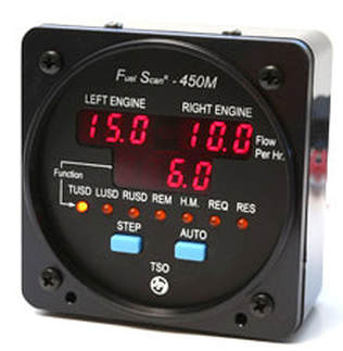 Airplane fuel gauges are somewhat similar to vehicle fuel gauges in that they both indicate the quantity of usable fuel present in the fuel tank. However, airplane fuel gauges work at a more complex level simply because aircraft carry more than one fuel tank and they also have more than one engine. Besides, reading fuel levels becomes complicated due to the fluctuating fuel density resulting from the changing aircraft altitudes.
To explain the workings of an airplane fuel gauge in a simplistic manner: a float level gauge is fitted to each of the fuel tanks in the aircraft. These gauges feed the information pertaining to fuel level in each tank to magnetic couplings and potentiometers which in turn pass on the information to the aircraft fuel gauge. However, the sloshing liquid with fluctuating density in multiple tanks make the work of airplane fuel gauges quite complicated. Modern aircraft technology however, has been able to achieve an advanced level of accuracy in the complicated world of aircraft fuel level reading. Basically, there are three types of airplane fuel gauges that are used in aircrafts of today, namely, 1) mechanical airplane fuel gauge 2) electric airplane fuel gauge, and, 3) digital airplane fuel gauge, which is the choice for the latest model of airplanes. The Mechanical Airplane Fuel Gauge is fitted with a cork which is attached to a lightweight aluminium pipe. The cork goes up or down with the fuel level. The pipe is attached to a stainless steal gear system which converts the motion of the cork into a circular movement showing “full” or “empty” indication of the fuel tank. The mechanical fuel gauge is a simple device found in the old aircraft models. The disadvantage of mechanical fuel gauges is that there are too many moving parts that can get stuck or jam up due to the aircraft’s movement and vibration. Electrical Airplane Fuel Gauge is also known as capacitance meter and uses a capacitor, an electrical amplifier and a fuel gauge to give a reading of Fuel Flow indicators in the tanks. The capacitor stores an electric charge, the size of the dielectric which is either the fuel in the tank when full or the air in the tank when it’s empty. The fuel gauge in the cockpit of the aircraft reads the capacitance charge and displays the information. The Digital Airplane Fuel Gauge is the latest technology being used to calculate the level of fuel in the airplane’s tanks. When the aircraft is fuelled up for a flight, the pilot enters the quantity in each tank via a touch screen on the Digital Aircraft Fuel Flow Monitors. The flow rate of the aviation fuel through the outlet pipe is accurately measured and the onboard computer in the plane’s electronic management system calculates the quantity of fuel remaining in each of the tanks and displays it in digital form or bar graphs. Based on the consumption of fuel and the quantity left in the tanks, the aircraft’s electronic management system can calculate whether the plane has sufficient fuel to reach its destination. Visit Here :- https://www.jpinstruments.com/ |
AuthorJ.P.Instruments was founded in 1986 in Huntington Beach, California, USA. Its founder, Joseph Polizzotto, is now the current CEO. Archives
May 2019
Categories
|

 RSS Feed
