Aircraft Flight Instruments
...The leader in aircraft engine data management systems.
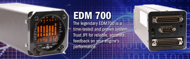 Having acquired the Aircraft Engine Data Management System 700 (EDM 700), it goes without saying, that this awesome piece of equipment needs to be carefully handled and installed.
While the JPI warranty at the back of the instruction manual clearly states that JPI will replace defective parts under warranty, it does not cover mishandling or defective installation. Care to be taken while installing the JPI EDM 700: 1. The JPI Aircraft Engine Data Management System 700 is packaged along with 4 screws. While fixing these screws, care should be taken to ensure that the four mounting screws should not penetrate the instrument more than 0.12 inches. 2. The person installing the EDM 700 must be a FAA certified aircraft mechanic. While we are sure there are many Do-it-Yourself pilots and aircraft owners out there, the installation of the Aircraft Engine Data Management System 700 is best handled by an officially (FAA) certified person who knows what he (or she) is doing. 3. Before installing the EDM 700, the mechanic should check if there are any STC (FAA approvals) available for the aircraft. 4. While installing the EDM 700, care should be taken to crimp ring terminals with a good crimping tool (e.g. AMP part 45518) crimp tool or equivalent. a. Ideal procedure is to fold back the wire double before crimping terminals – about 1/4" 1 1/2" b. Fold back wire double before crimping terminals 2 1/4" of Thermocouple wire harness red and yellow 5. Installation of the EDM 700 will require some parts that are likely to be unique to your make and model of aircraft hence these are not part of the EDM 700 kit. The instruction manual will guide the mechanic as to the parts that will be required. All necessary parts should be acquired prior to the installation. 6. While acquiring parts, care should be taken to not buy/use any aluminium fittings with the FXT-201 or FXT-231 Fuel Flow Transducer. 7. Before installation note the K-factor engraved on the side of the Fuel Flow Instruments. 8. Carefully select and mark the location of all the holes before drilling ensuring that nothing will interfere with the wires, probes, clamps and screws. 9. It is a good idea to provide service loops at the instrument – this will come in handy during future maintenance work. 10. Provide service loops for thermocouple wire too as it will allow you to swap OAT Probe on adjacent cylinders for future troubleshooting purposes. 11. Ensure all wires are kept away from high temperature components such as exhaust stacks. 12. Thermocouple wire should not be spliced using copper wire. Only K-type thermocouple wire. 13. Solder using zinc chloride flux such as Nokorode brand – rosin flux alone won’t work. 14. When connecting wires to probes, ensure correct polarity. 15. This instrument must be grounded at the engine, not at the avionics ground. More information at: https://www.jpinstruments.com/shop/edm-700/
0 Comments
 The Carburettor Temperature Probe (CRB) is used to detect temperature drop in the carburettor.
For successful ignition to occur, the air-fuel mixture has to be perfect and this can only happen at the right temperature. Now when fuel and air is mixed, the temperature inside the carb will drop dramatically and this is compounded due to external cold air and cold temperatures. Next thing you know – the carburettor is frozen solid – and this is not something you want to happen when flying; not by a long shot. So, the carburettor is kept warm and steady at its ideal temperature through a rather ingenious way by installing an anti-icing system and using air heated by the aircraft engine. This marvel of modern aviation engineering keeps the aircraft carburettor as warm as a kitten sleeping next to a fire. Not too hot – just right temperature keeps the kitten and carburettor happy. But an aircraft being what it is i.e. an amalgamation of thousand different parts; moving and non-moving, anything can happen so the pilot needs to know the moment the carburettor is not too comfy because it’s impact on the engine and aircraft can be far reaching and catastrophic. Enter the CRB probe. The Carburettor Temperature Probe (CRB) is connected either to an independent analog or Digital Gauges (the type of probe used will depend on type of display you have in the cockpit). The moment the pilot detects a drop in the carburettor temperature, he can start the pre-heater and it will heat the air flowing over the carb thereby preventing the carburettor from freezing over. To ensure accurate temperature reading, the Carburettor Temperature Probe (a sensor), is mounted directly on the carburettor wall. This, along with other indicators (e.g. drop in RPM, rough sound etc.) serve as a warning to the pilot(s) that all is not well. Modern CRB probe like those manufactured by J.P. Instruments, are meant to be immune to factors such as oil, humidity and gasoline. They are also engineered to withstand wide temperature fluctuation. Each CRB has a sensing coil within it. This coil is fully coated in an epoxy resin which in turn sits within a metal tube thick enough to withstand repeated backfires, but thin enough to be highly sensitivity to temperature change. This fine balance is perfectly achieved by only a few CRB manufacturers and J.P. Instruments is one of them. The CRB Probes being delicate, should be handled with kid gloves i.e. fit it gently but firmly avoiding the use of harsh tools such as hammer or pliers. The maximum tightening torque should be no more than 4 foot-pounds. The single-spacing washer that is provided should contact the carburettor casting, and the lock washer should be in contact with the shoulder on the probe. Use counterbore to ensure the CHT Probes reaches all the way into the carburettor barrel. The counterbore will reduce the thickness of the casting slightly at the outside of the hole. Recommended torque is no more than 3 to 4 foot-pounds. For more information on aircraft CRB probes, please visit https://www.jpinstruments.com/shop/crb-probe/ 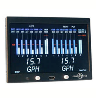 The best EDM that money can buy in under ten thousand dollars (U.S) for 4 or 6-cylinder aircraft engine with transducers and all? The answer has to be EDM 790 manufactured by J.P. Instruments, U.S.A.
It’s not just an advert claim, the Engine Data Management 790 system is truly the most advanced twin piston engine-monitoring instrument on the market. The EDM 790 has been TSO’s for quality and is rightly thought of as a Flight Engineer and Maintenance Manager that has your back covered. Covers to 29 critical parameters Armed with the latest microprocessor technology, the EDM 790 will monitor up to 29 critical parameters of your aircraft engine – 4 times a second! It boasts of a linearized thermocouple accuracy of better than 0.1 percent or 2 F° and this boast has been tested and verified by the FAA. It never sleeps Constantly on the alert, the EDM 790 will keep an eye for you on 29 critical parameters that are automatically checked four times every second. No matter which screen you might be currently looking at, the EDM 790 will keep running checks on all 29 parameters in the background. Accuracy The EDM 790’s accuracy stems from its linearized thermocouples. There is nothing in the aviation market that compares to J.P.I’s linearized accuracy. Simplicity Two buttons on the faceplate is all that it takes to programme the EDM 790 or to access all its functions. Leaning is accomplished automatically using the Lean Find procedure. With the EDM 790 it is now possible to have substantially more diagnostic information available for your maintenance crew. The Advantage of EDM 790 1. Computer Assisted Diagnostics covering the entire aircraft system from the cockpit. On detecting any error, the specific code is displayed. 2. Easy-to-use 2-button programming. 3. Twenty-nine parameters checked 4 times a second and this includes the EGT Differential, Alternator Voltage, Fuel Flow and Shock Cooling. 4. Displays variable Scaling of EGT Bar Graph. 5. Its amazing Lean Find Mode identifies the first and last cylinder to peak while the Peak Find with quick responding probes, automatically captures the EGT or TIT Probes peak value. 6. Data Port for downloading of data. 7. The EDM 790 is the only FAA approved graphic engine monitor with a complete fuel flow system. 8. Temperature detection accuracy is ONE degree (even for EGT). 9. Paired with JPI’s “grounded” fast response probes. 10. Cooling rate and shock cooling checked on each and every cylinder. 11. EDM 790 features a “Normalize Mode” for accurate trend monitoring. Bars are in 10o increments. 12. Alphanumeric scanning display of 29 functions or channels. 13. TSO’s for Quality and Reliability with FAA, STC approved Fuel Flow Indicators. 14. Three-year warranty. For more information, please visit: https://www.jpinstruments.com/shop/edm-790/ 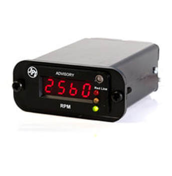 There was a time when portable watches used to be two inches in diameter and as much as three-quarters of an inch thick. These watches were kept in the pocket and taken out only when you needed to know the time.
We all know how these pocket watches evolved, became slimmer and turned into wrist watches. The display gauges in the aircraft cockpit underwent a near identical transformation except that; on the evolution time-scale, they evolved nearer the electronic revolution so instead of becoming slimmer versions of their earlier self, they turned into slim line digital gauges. Naturally, the sensor that actually picked up the aircraft engine data also got transformed and began transmitting data in electrical pulses that could be interpreted by the smart electronics circuits inside the slimline gauges. In next to no time the integrated circuits got so miniaturized that an entire circuit was fitted inside a single chip 2 x 1 cm in size which came to be called the IC chip (short for integrated circuit). During this same period, onboard memory was developed which totally transformed the way data was handled and interpreted because data could now be temporarily stored, recalled and used – almost in the same way as your calculator memory. Next came a permanent memory module – the Random Access Memory (RAM). Thanks to this new development, instead of data being lost when the aircraft engines were turned off, critical engine data could be stored and retrieved on a semi-permanent basis. Along with the miniaturization of the innards of the slimline gauges in aircraft, the front end i.e. the display itself underwent a change and the humble analog dial was replaced with a Liquid Crystal Display (LCD). So now the pilot could see the actual digits. This was also the time the analog wrist watch began to get replaced with a digital wrist watch. This was also the time when electronic pagers began to make their appearances in the market. The next big development occurred when the memory modules was linked to the faceplate of the Slim Line Gauges which totally revolutionized and enhanced the value and usefulness of the slimline gauge. The pilot could now directly interact with the gauge by feeding in alarm triggers in the form of upper and lower limits. For example, minimum temperature and maximum temperature. These figures would be stored in the memory module and constantly compared with the incoming temperature data. So, if the temperature fell below the minimum figure or rose above the maximum figure, an audio-visual alarm could be triggered. This meant the pilot(s) no longer needed to keep monitoring the gauges and instead, could actually enjoy the flight. Each slimline gauge usually displayed one piece of information. So, you had a slimline gauge for Oil temperature, OAT Probe, RPM Sensor, Voltage, Manifold Pressure, OIL Pressure and so forth. As of today, individual sensors pick up the data directly from the engine and transmit it as a voltage via wires to the individual slim line gauge for which it is meant. The electronic board and IC circuit onboard the slim line gauge interprets the incoming voltage, converts it into a meaningful number and displays it on the screen. The display was bright enough to be seen even with the sun directly behind the pilot. For options on modern slim line gauges, please visit: https://www.jpinstruments.com/shop/slim-line-experimentalhomebuilt/ |
AuthorJ.P.Instruments was founded in 1986 in Huntington Beach, California, USA. Its founder, Joseph Polizzotto, is now the current CEO. Archives
May 2019
Categories
|

 RSS Feed
