Aircraft Flight Instruments
...The leader in aircraft engine data management systems.
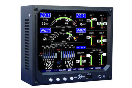 The engine data monitoring system (EDM) 960 – the one manufactured by J.P. Instruments is available for all aircraft with 4, 6, 7, 8 or 9 cylinders engines. There are so many things in an aircraft that need to be monitored that in days gone by, there used to be a flight engineer whose job it was to keep an eye on the engine performance during flight.
But the flight engineer was only human and during long flights, it was easy to not notice some things. But being a machine albeit an intelligent one; the EDM 960 system electronically surveys everything it is connected to, and it does it four times a second. Nothing can escape its attention. Some of the characteristics of the EDM 960 System: The EDM 960 not only reads the data sent to it by the sensors, it has the ability to compare that data with extreme values pre-entered into the system by the pilots and; in the event that any sensor reading of the aircraft engine does not confirm to the pre-entered values, it will trigger an audio-visual warning. Apart from this, if you plug the appropriate GPS, it can calculate time-to-empty in real time based on actual fuel in the tank. It can compute distance, calculate fuel requirement (based on current fuel use rate), compare fuel requirement with available fuel and display data on whether you can make it to a way-point or not. The EDM 960 System acts like your very own flight engineer – one that never feels drowsy or sleeps during a flight. Specifications of the EDM 960 Twin System manufactured by J.P. Instruments: 1. Lean Find™ finds the first and last cylinder to peak with true peak detect eliminates false peaks 2. Hands-free, automatic scanning 3. Displays both leaned temperature below peak and peak 4. All programming done from the Front Panel 5. Battery voltage with alarm 6. Programmable alarm limits 7. Amperes (load or charge/discharge meter) 8. Normalize view 9. DIF low to high EGT with alarm 10. Exhaust Gas Temperatures (EGTs) to stable 1°F resolution 11. EGTs to stable 1°F resolution 12. User selectable index rate 13. Shock cooling monitored on every cylinder 14. Fast response probes 15. Records and stores data up to 30 hours 16. Non-volatile long-term memory 17. Post-flight data retrieval 18. Data retrieval software 19. Download to Palm™ Computer 20. Fuel level display 21. Oil pressure 22. Outside air temperature 23. Oil temperature 24. Adjustable display 25. Adjustable order of display Other characteristics of the EDM 960 System include: Display via liquid crystal display (LCD) screen as well as remote auxiliary display (RAD) (if connected). The default displays of the EDM 960 Twin System include fuel pressure, oil pressure, oil temperature, bus voltage amps, fuel flow (left and right separately), and outside air temperature. Without doubt, the EDM 960 is an invaluable safety device for the pilot and his aircraft. It helps diagnose engine malfunctions, adjust air-to-fuel mixture, provide real time feedback on the critical components of the Aircraft Engine Monitoring Systems as well as diagnose air craft position vis-a-viz destination and compare it to fuel status (provided you have the right GPS installed). You can find more information here: https://www.jpinstruments.com/shop/edm-960/
0 Comments
 For this article, we’ve selected to explain the working principles of the RPM standard sensor for the pressurized Bendix series (manufactured by Teledyne Continental Motors):
The RPM sensor is connected to the magneto. To understand the sensor let us first begin with the “why” of things i.e. why is the magneto required in the first place is: A magneto is required to power the sparkplug. Every combustion engine (including those used in aircraft), have sparkplugs. These provide the ignition or fire required to ignite the fuel-air mixture in the combustion chamber. The sparkplug purpose and functioning are identical to the gas lighters that your mom used to have; but are now built into the gas range in your home. To work properly, the sparkplugs in turn require an awful lot of electrical volts to create the spark. And this electrical power needs to be very precise and delivered at the right moment. A battery would not do the job efficiently so a custom-built power generator called the “magneto” was invented. As the output power from the magneto needed to be precise, it therefore needed to function with precision. A malfunctioning magneto will mean that everything downstream will also malfunction. So, the pilot(s) need to know the instant the magneto isn’t working as intended. Enter the RPM sensor. To understand the working principle of the RPM sensor, it is important to know a bit about the magneto itself. The Magneto is basically a dynamo with a rotating magnet, a built-in breaker switch, a transformer and a distribution system to channel the power to the spark plugs. For reasons mentioned above, it is important that the magnet rotates at a speed that is within the prescribed range otherwise your spark plugs (and hence the engine) will misfire. To ensure that is so, you need the aircraft RPM Sensor. The RPM standard Sensor plugs directly into the magneto and transmits data to your EDM/ RPM gauge in the cockpit. The Aircraft Sensor Systems you use will depend on the magneto brand and model inserted in your aircraft. If you need to install a new RPM sensor, make sure: • The new RPM sensor is precisely aligned with the correct vent plug of the magneto. Here’s how you do it: peep into the magneto hole and you should see the rotating magnet in this hole. If you see anything other than the rotating magnet e.g. the ‘gear’, then you’re on the wrong vent. • When everything is connected and the engines fired up, the Digital Gauges in the cockpit should read 2400 rpm for a 6-cylinder engine or 1800 rpm for 8-cylinder or 1600 for a 9-cylinder engine. If you have a 4-cylinder engine with a dual mag, the rpm should be 1800 and for a 6-cylinder engine with dual mag, it should be 2400. • The red wire to the RPM standard sensors should be supplying 5v+. More information on JPI manufactured RPM standard sensors here: https://www.jpinstruments.com/shop/rpm-sensor-for-bendix-mag/ 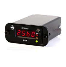 Back in the days of WWII, aircraft cockpits had few dials (gauges) and each was connected to any individual part of the aircraft engine. As aeroplane design improved so did the number of gauges in the aircraft cockpit.
Overtime, the aircraft cockpit got so crowded with gauges that it was impossible to keep track of all the information that was being displayed. The pilot would look at the gauges that were critical to the flight and just eye-ball the rest and hope for the best. These gauges did not have any alarm system so, more often than not the flight crew usually found out about a problem the hard way - when the engines began to ‘cough’ and sputter. It is said that necessity is the mother of invention and clearly, when it came to the post WWII aircraft, there was an urgent necessity to improve the way information was displayed in the cockpit. The one area that technology leap-frogged, was in electronics. The first super computer was invented and it could analyse millions of bits of information every second. So instead of continuing to use analog gauges, aircraft manufacturers and after-market component makers such as J.P. Instruments, began to see electronics and digitization as an ideal way to display engine data. But before the humble analog gauge went digital, there was need to improve the way data itself was collected and transmitted. Enter the modern sensors. Earlier Aircraft Sensors were thicker than your fingers and slow to react. Worse, some had mini moving parts (e.g. fuel sensor) inside them that would get stuck during flight. Around the time electronics leap-frogged, new space age technology gave birth to space-age materials that helped overhaul the aircraft engine sensors. The new sensors became ultra slimline, responded to changes very fast and became more accurate. Simultaneously, the cables that transmitted the data too became ‘Slimline’ and interference-free. Enter the new and modern slim line gauges (so called because they were less than two inches in height). The feed coming directly from the sensor was attached to each slim line gauge. So, you had a slim line gauge for OAT Probe, Voltage, Oil Temperature, RPM, Manifold Pressure, Fuel Pressure, Oil Pressure, TIT and so forth. How Slim Line Gauges work The individual sensors pick up the data directly from the engine and transmit it as a voltage via wires to the individual slim line gauge for which it is meant. The electronic board and IC circuit onboard the slim line gauge interprets the incoming voltage, converts it into a meaningful number and displays it on the screen. The display was bright enough to be seen even with the sun directly behind the pilot. A new amazing feature was added into the slim line gauge – thanks to its IC circuit, it could compare the incoming data with pre-entered data coded into the IC chip. Two or three LED bulbs were added to the gauge. So, for example, if the RPM Sensor count was normal, the green LED bulb would light up. If the RPM went up the yellow LED bulb would like up and if the count exceeded specified limits, the red LED bulb would light up. This was a huge relief for the pilot as he only needed to look at the gauge if any LED other than green lite up. For options on modern slim line gauges, please visit: https://www.jpinstruments.com/shop/slim-line-experimentalhomebuilt/ |
AuthorJ.P.Instruments was founded in 1986 in Huntington Beach, California, USA. Its founder, Joseph Polizzotto, is now the current CEO. Archives
May 2019
Categories
|

 RSS Feed
