Aircraft Flight Instruments
...The leader in aircraft engine data management systems.
 This question comes up often enough so we decided to write on how best to install the fuel flow transducer model 201B manufactured by J.P. Instruments in an aircraft.
Orientation of the 201B fuel flow transducer: To start off and assuming you have removed the existing fuel flow transducer, hold up the new 201B fuel flow transducer in a horizontal position with the three wires up – because this is exactly how it is to be fitted. Fitting the fuel flow transducer any other way will lead to its failure. When the fuel flow transducer is in the horizontal position, the rotor within it are proper oriented and aligned with fuel flow. This is how it is meant to operate. Also, while fitting it, be sure that there is no bend closer than 6 inches either in the inlet or outlet pipe i.e. no bends before or after the transducer. Also, do not use aluminium or brass fittings when installing the 201B fuel flow transducer – use only AN816-7 Steel. The transducer is engineered to seal tight so do not use Teflon tape, or other thread sealant compound of any kind. Also, the transducer is marked IN and OUT for the fuel lines – so make sure you attach it correctly or the rotor will malfunction. The maximum torque should not exceed 15 ft lb (180 lbs.) or roughly, two full turns past hand tight. Installation location: If your aircraft has a carburettor, the fuel flow transducer should ideally be at the same height as the carburettor. If it is higher, fit an anti-siphon loop in the line that peaks higher than the transducer. If your aircraft sports a fuel injected engine, fit the fuel flow transducer between the engine fuel pump and the servo regulator. If your aircraft has that unique vapor return line, install the fuel flow transducer between the servo regulator and the flow divider (spider). We have seen aircraft with Fuel Flow Instruments mounted between the electric boost pump and the mechanical pump – this is not recommended. Also, please do not hard mount the transducer to the engine as engine vibration can damage the internal rotor or cause it to malfunction and give misleading results. When installing the 201B fuel flow transducer, the wires are to be connected to the EDM. The fuel flow transducer gets its power supply (12V) directly from the EDM. Also, the wires should not be route along with or adjacent to ignition wires, alternator wires, spark plug leads, or cabin heater ignition wires. When done, set the K-factor. The Fuel Flow Transducer 201B will have a K-factor of ~29. Testing: It might be worthwhile to also procure a Fuel Flow Tester (just $35.00) for testing instrument and transducer. Fault finding: Some pilots called in to report consistently high fuel flow readings. If you have followed above installation procedure correctly, check for air entering system at selector valve (may require a change of the O-ring). Here’s a test: The next time the aircraft is flown in cruise, turn on the boost pump for one minute. If the fuel flow drops, then this is an indication that air is leaking into the fuel line upstream of the transducer. It is possible that air is leaking into the system through the seal valve or other connection. Fuel stain may not be visible. Visit Here:- https://www.jpinstruments.com/
0 Comments
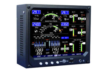 EDM 960 manufactured by J.P. Instruments is available four, six, seven, eight and nine-cylinder aircraft engines configurations. The EDM 960 is designed to be a pilot’s personal flight engineer – one that is always working in the background and constantly watching over the aircraft engine while the pilot concentrates on flying the aircraft.
The EDM 960 actively monitors the aircraft engine four times per second and sound/ display a warning if any part of the aircraft engine does not confirm to the pre-set parameters. Here are the specifications of the EDM 960 Twin System manufactured by J.P. Instruments: 1. Hands-free, automatic scanning 2. All programming done from the Front Panel 3. LeanFind™ finds the first and last cylinder to peak with true peak detect eliminates false peaks 4. Displays both leaned temperature below peak and peak 5. Battery voltage with alarm 6. Amperes (load or charge/discharge meter) 7. Programmable alarm limits 8. Normalize view 9. Exhaust Gas Temperatures (EGTs) to stable 1°F resolution 10. DIF low to high EGT with alarm 11. EGTs to stable 1°F resolution 12. Shock cooling monitored on every cylinder 13. User selectable index rate 14. Fast response probes 15. Non-volatile long-term memory 16. Records and stores data up to 30 hours 17. Post-flight data retrieval 18. Download to Palm™ Computer 19. Data retrieval software 20. Oil pressure 21. Oil temperature 22. Outside air temperature 23. Fuel level 24. Adjustable display 25. Adjustable order of display These are the main features of the EDM 960 Twin System: The EDM 960 displays engine measurements on a liquid crystal display (LCD) screen and also on a remote auxiliary display (RAD). The RAD intelligently places critical information directly in front of you. After the initial self-test, the pilot will be requested to punch in the fuel information i.e. total fuel added or fuel in the tank. The RAD unit will also display the rpm and manifold pressure. The display screen is divided into three sections – top left is for the rpm and manifold pressure. The bottom left is the scanner section while the right side of the display is for the bar graphs. The bar graph also displays the numerical values of each bar. If any power settings exceed pre-programmed limits, a blinking alert icon along with a blinking message is displayed in the scanner section. The default displays of the EDM 960 Twin System include oil temperature, oil pressure, fuel pressure, bus voltage amps, outside air temperature, fuel flow (left), fuel quantity and (right side) fuel quantity. The EDM 960 collects data and displays it for you in a useful way. The EDM 960 monitors engine temperatures, pressures, fuel quantities, fuel flow, and voltages. It is invaluable for adjusting the fuel air mixture and for diagnosing engine malfunctions. On the left of the display is the EGT Probe graphed. There's also the CHT Probes graph and below it the number corresponding to the engine cylinder number. There are four buttons on the front panel. The button labels can be changed depending on how the display has been arranged by the pilot. The features of the EDM 960 Twin includes auto indexing i.e. 10 minutes after the EDM 960 is turned on it will automatically index through all measurements. Tapping the step button will take you into the manual indexing mode here you can observe each measurement value for as long as you want. You can find more information here: https://www.jpinstruments.com/shop/edm-960/  The Compressor Discharge Temperature (CDT) probe (not to be confused with Conductivity, Temperature, Depth probe used in ships and also called CDT probe), is installed in the engine compartment just after the inter-cooler. The probe is installed with a #40 stainless steel clamp. A large clamp is supplied to fit around the air-port leaving the inter-cooler.
A typical CDT probe kit from J.P Instruments includes the thermocouple type ‘K’ CDT Probe, a stainless steel clamp thimble, one stainless steel exhaust seal washer and one stainless steel screw type clamp. Working of the CDT in an aircraft: The CDT probe senses compressor discharge temperature of the aircraft compressor and for this purpose, the probe is mounted external to the flow path that receives high pressure air discharged from the compressor. This air flows past at least one thermocouple which in turn measures the high-pressure air temperature and the high-pressure air is then returned to the flow path. Basically, air from the compressor is discharged through a hole bored into the engine case. This air is then channelled into a housing containing the CDT probe which measure the air temperature flowing over it. The CDT probe in turn sends an electrical signal to the connected Engine Monitors or electronic control unit which in turn indicates the compressor discharge temperature to the pilot. The air is then vented to a sink pressure and can be used as cooling or purge flow. The purpose of wanting to know the comp discharge temp is to prevent chances of detonation that can happen due to excessive heat. The intercooler cools the air so much that the limit temp is never reached, or even approached, so the original equipment CDT gauge becomes irrelevant. Fundamentally you want to know the inlet temp limits for the engine and the temp of the air at this point. If the CDT is below this temp, you are fine. If CDT is above this, it depends on the conditions and the efficiency of the intercooler (or aftercooler as is technical called ). As we are aware, CDT can be critical under certain circumstances e.g. staging a dual annular combustor for a high bypass turbofan commercial jet engine where fuel-to-air ration can be critical. JPI CDT probes are superior because of their response speed. Ungrounded (insulated) probes sold by rival manufacturers are too slow to respond to all temperature changes. It is also worth noting that insulated probes, starting at the same point as grounded probes, never achieved true temperatures. The ungrounded, insulated probes are generally 3/16" in diameter whereas, JPI's grounded probes are only 1/16" in diameter. The Oil Temp Probes manufactured by the rivals have more surface are and therefore lose energy a rate of T'/ This is another reason JPI uses thin probes and not sluggish probes. Also, JPI's grounded probes are manufactured using a space-age material, Hastaloy-X, that can withstand the harsh sulphur atmosphere of temperature exhaust gas and uses them in all its gages. You can select and buy CDT Probes here: https://www.jpinstruments.com/product-category/probes-sensors/ 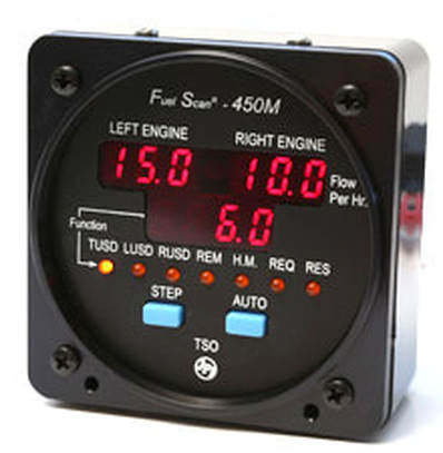 The aircraft fuel scan 450 Twin manufactured by J.P. Instruments, is probably the best fuel indicator to date. This is a product engineered by aeronautical engineers (nothing new there), but; hold your breath, was designed by bunch of experienced pilots which is why it has all the features and functionality that you as the pilot or aircraft owner might love to have in a fuel indicator.
I won’t insult your intelligence by writing that this is a digital fuel indicator! Of course, it is digital – which modern day fuel indicator isn’t? That said and for its size, it uses an amazing display system – one that is not only crystal clear, but has the priorities right. So, let us check out the features offered by aircraft fuel scan 450 Twin manufactured by J.P. Instruments. Product features of by aircraft fuel scan 450 Twin manufactured by J.P. Instruments 1. Fuel quantity measured in gallons, litres or pounds. 2. Low fuel quantity alarm. 3. Low fuel time alarm. 4. GPS interface—bi-directional serial interface. 5. Automatic K-factor calculation. 6. Instantaneous fuel flow rate 7. Solid-state pulse generating rotor fuel flow transducer. 8. Total amount of fuel consumed. 9. Total fuel remaining. 10. Time to empty at the current fuel-flow rate. 11. Fuel Management. One thing that obviously hasn’t changed is the fact that the pilot has to still enter the quantity of fuel filled into the tanks. He can do so while the aircraft is on the ground or even after take-off. Naturally, the accuracy of some of the functions of the aircraft fuel scan 450 Twin depends on accuracy of the fuel quantity entered by the pilot. That said, let us see how different the aircraft fuel scan 450 Twin vis-à-vis earlier fuel indicator models. For starters, the FS-450 Fuel Scan uses a small, highly compact turbine transducer that measures the fuel flowing into the engine. The working principle of the transducer is similar to that of a regular power generator – the faster the wheel spins, the more the power output. This ingenious simplicity ensures that the transducer keeps performing accurately even if the aircraft was doing cartwheels in the air. In terms of accuracy, fuel transducer does to the fuel indicator what HD technology did to your TV set i.e. the high rate of pulses generated by the High Flow Transducer, ensures higher accuracy in calculating fuel flow. Having the fuel flow accurately measured; thanks to modern day IC-based circuits and programming, the rest of the requirements on the pilot list was easy to implement. The functionality of the aircraft Fuel Scan 450 Twin manufactured by J.P. Instruments includes: Operating Modes: There are two operating modes – Automatic Indexing, and Manual Indexing. Programmable Alarms: Pilot programmed minimum Fuel Flow Instruments that will display fuel remaining and finally, time of flight left until the tanks become empty. Sleep Alarm: Don’t want to be distracted by the alarm? Just press the STEP button and the alarm will ‘sleep’ for 10 minutes or, press and hold a couple of seconds and the alarm will turn off. Automatic Self--Diagnostic testing on engine start after which, it will remind you to enter fuel you might have added to the tanks. These and several other functions and features, make the aircraft fuel scan 450 Twin manufactured by J.P. Instruments an awesome product. It is hardly surprising therefore, that it has been declared as the best aviation consumer product for this year. More information here: https://www.jpinstruments.com/shop/fuel-scan-450-copy/ |
AuthorJ.P.Instruments was founded in 1986 in Huntington Beach, California, USA. Its founder, Joseph Polizzotto, is now the current CEO. Archives
May 2019
Categories
|

 RSS Feed
