Aircraft Flight Instruments
...The leader in aircraft engine data management systems.
 Here are the top 10 tips on installation of a Turbine Inlet Temperature (TIT) probe in your aircraft:
1. Before you even open the package containing the TIT probe, you need to do a little planning i.e. determine the exact location of hole for placing the TIT probe and while doing so, ensure that there is nothing nearby that would interfere with the probe, clamp, clamp screw or wire of the TIT probe. 2. Provide service loops at the instrument – you don’t want to run out of wire during maintenance at some future date. 3. Provide service loops at the engine end as well so that the probe can be swapped to adjacent cylinder positions for troubleshooting purposes. 4. Ensure all wires are kept away from any high temperature components such as exhaust stacks. 5. Ideally, do not splice thermocouple wire using copper wire. We also do not recommend soldering the thermocouple wire. But if you have no other option, solder using zinc chloride flux such as Nokorode brand – not rosin flux. 6. When making the connection, double check the polarity of your Oil Temp Probes wire. 7. The standard TIT probe PN M111-T for Aircraft Engine Monitor comes equipped with a #48 clamp that is placed in the exhaust stack accumulator to a maximum depth of 1/2 inch and approximately 4 inches from the turbine inlet if possible, on the wastegate side of the turbine. 8. Here is a list of things required for installation of the TIT probe: I. Slim Line Display (if you haven’t fitted one already), 2 mount. Screws: 1 II. Thermocouple Wire 8’ III. Molex 0.256” Connector Pins: 2 IV. Connector housing: 1 V. Stainless Steel Clamp Thimble: 1 VI. Stainless Steel Exhaust Seal Washer: 1 VII. Stainless Steel Screw Clamp #48: 1 VIII. M-111 Thermocouple Probe: 1 9. If the has been fitted properly than the reading on your panel should be 1650 Fahrenheit. 10. TIT Probe installation schematic: More information here: https://www.jpinstruments.com/shop/tit-probe/
0 Comments
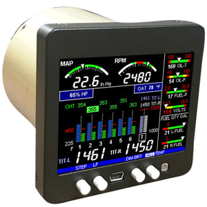 The aircraft Engine Data Manager 350 (EDM 350), by J.P. Instruments is a small box-like device with an LCD screen on the front and it keeps track of the vital functions of the aircraft engine.
The faceplate requires just 3.25 square inches of space on your aircraft dashboard and is easily fitted. Although physically small in size, this little gadget is packed with electronic chips that analyse 24 different engine functions in any 4-cylinder aircraft. The basic 4-cylinder EDM 350 kits start at just $798 while the 6-cylinder EDM 350 kits are priced at $988. Both representing enormous value for money. Fitting the EDM 350 is as easy as can be – first, attach all the probes to the engine and thread them out of the empty space 3.25-inch space. Next, attach the probes and wires to the EDM 350 and ‘plug-in’ the EDM 350 Aircraft engine data manager into the empty socket. That it, you’re good to go. How the EDM 350 works: The EDM 350 is like a little on board computer. It has ‘high‘, ‘low’ and ‘normal’ figures for 24 different engine parameters pertaining to 2 ~ 4 cylinder aircraft engines. Once the aircraft engine is switched on, the 24 sensors attached to different parts of the aircraft engine, pickup data and transmit the same via wires to the EDM 350. As the data begins to flow in, the EDM 350 begins to display the information on the LCD screen. The information may be displayed graphically or in actual numbers depending on how the pilot wishes to view the information. So long as all parameters are in the ‘normal’ range it simply displays the data. If however, any parameter is in the ‘low’ or ‘high’ range, an audio-visual alarm is triggered. The ‘lows’ and ‘highs’ can be entered manually by the pilot. With the Aircraft Engine Data Management 350 on board, the pilot is free to fly the plane and enjoy the experience rather than having to concentrate constantly the status of the engine. Here are the 24 different engine parameters that the EDM 350 keeps a watch over: 1. CHT - Cylinder head temp - probes and harness included. 2. EGT - Exhaust gas temp. 3. VDC - Voltage display. 4. ROP/LOP - Lean finder. 5. CLD - Shock cooling on all cylinders. 6. DIFF - Engine health. 7. Internal Memory - Enough memory to record 600 hours of data (recorded every 6 seconds). 8. USB Port - Convenient data port for quick and easy download of engine data. 9. EZTrends Software - Graphics software with Google Earth location included. 10. MAP - Engine Manifold pressure. 11. RPM - Prop rotation speed. 12. O.T. - Engine oil temp. 13. F.P. - Fuel pressure. 14. O.P. - Engine oil pressure. 15. OAT - Outside air temp. 16. CRB - Carburettor temp. 17. TIT - Turbine inlet temp. 18. CDT - Compressor discharge temp. 19. L-R-Main - Fuel quantity in all tanks. 20. AMP - Battery load output in amps. 21. V-2 - Second volts readout. 22. % HP - With FF, OAT and RPM. 23. Amp-2 - Second load readout in Amps. 24. FF - Fuel flow includes: • GPH - Gallons per hour. • REQ - Fuel required to way point / destination. • USD - Fuel used. • H:M - Endurance in hours and minutes. • MPG - Miles per gallon Notes: 1.EGT probes must be mounted 2 to 4 inches from aircraft cylinder head. 2.If EGT clamps are too short, please buy larger clamps (available with J.P.I) 3.If EGT probes appear to be lose, please remove the probe, squeeze the thimble and reassemble. 4.Existing TIT Probe cab be used only if the aircrafts TIT probe has the same type thermocouple. For more information on EDM 350 Aircraft engine data manager by J.P. Instruments, please visit: https://www.jpinstruments.com/shop/edm-350/  The CHT Bayonet probes are the threaded probes and are commonly known as ‘CHT Bayonet Probes’. These are typically used on Lycoming engines in aircraft.
Let us start with extending the CHT probes - most CHT probes available in the market feature cold-junction compensation. Cold-junction compensation means that the temperature of the cold junction of the thermocouple is measured (at the RDAC) and this temperature is used to compensate for ambient temperature with the small voltage readout between the two alloys at the thermocouple junction. For this reason, it is important that type-K extension wire be used for type-K thermocouples. You can use the same extension wire for EGT’s and CHTs. The length (within reason), is not critical and will have little or no effect in the temperature reading. Installation of CHT Bayonet probe in aircraft is actually quite simple: 1. Begin by screwing in the threaded CHT probes into recesses in cylinders (3/8-24 - no washers are required) 2. Use Thermocouple Channels TC5 through TC8 if you have a 4-cyl engine and TC7 through TC12 if you have a 6-cyl engine. 3. Remember that some CHTs are type-J thermocouples (these can be used). 4. Remember that with type-K thermocouples that Yellow is Positive and Red is Negative. There CHT Probes & Sensors extension kits available in the market and most include the type-K thermocouple wire, splice barrels, and a length of inner heat shrink tubing. When heated, this heat shrink gets quite soft inside and this eliminates all air inside the splice and makes an airtight seal. If required you and use heat shrink and we recommend you use Raychem SCL-3/16 heat shrink. Here’s how you extend the wires of CHT Bayonet probe in Electronic Data Management Systems : 1. Use a wire stripper to strip the CHTs and make small loops with the ends. 2. Do the same with the type-K extension wire (if extension is required). 3. Prepare the splice barrels and heat shrink. 4. Place a splice barrel and short length of shrink wrap on the wires. 5. Lay the CHT and type-K extension loops over each other. 6. Slide the splice barrel over the parallel loops. 7. Crimp the splice barrel with a crimping tool (use a crimping tool with a grip for non-insulated terminals –the ones that have a cradle on one side and pierce a small hole on the other). 8. Slide the heat shrink over the splice and heat with a heat gun or lighter. 9. That is a solder-free, airtight and airless parallel thermocouple splice. For ordering or more information, please visit: https://www.jpinstruments.com/shop/cht-bayonet-probe/ |
AuthorJ.P.Instruments was founded in 1986 in Huntington Beach, California, USA. Its founder, Joseph Polizzotto, is now the current CEO. Archives
May 2019
Categories
|

 RSS Feed
