Aircraft Flight Instruments
...The leader in aircraft engine data management systems.
 The aircraft engine data manager is something you select carefully and install - usually just once in your life-time. For this reason, J.P Instruments have made sure that their engine data managers for experimental aircraft are absolutely the best that money can buy and this goes for the EDM 740 too.
0 Comments
 Current aircraft flying around in the skies have either the analog fuel flow instrument (aircraft 10+ years old), or have the new digital version. While the analog ones simply display the balance fuel quantity, the digital version (depending on the model), provide a whole host of important information.
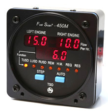
Aircraft owners who have opted for after-market fuel flow instruments, usually install the fuel scan 450 Twin manufactured by J.P. Instruments, and is probably the best fuel indicator in the market. Typically, modern-day fuel flow instruments (depending on brand and model), offer lots of information in real time including: 1. Fuel quantity alarm. 2. Pilot selectable quantity display in gallons, litres or pounds. 3. Interface with GPS (depending on the brand and model). 4. Automated K-factor calculation. 5. Real-time fuel flow rate. 6. Solid-state pulse generating rotor fuel flow transducer. 7. Total fuel consumed and fuel balance. 8. TTE - Time to empty at the current fuel consumption rate. 9. Fuel Management. After a refuel, the pilot manually enters the quantum of fuel filled into the tanks. From there on, the digital fuel flow instrument takes over. It goes without saying, that the accuracy of fuel balance and time to empty will depend on the accuracy of the figure entered by the pilot. Typical problems include fuel figure entered in gallons while fuel flow instrument is set to litres or visa-versa. If the fuel flow instrument is paired with a GPS then the fuel-to-next-way-point figure will also depend on the initial fuel input figure. Modern digital Fuel Flow Instruments use a small and highly compact turbine transducer that is fitted into the fuel outlet pipe itself and measures the fuel flowing into the engine. The fuel transducer works in an identical way to the spinning water wheel. This ingenious design paired with modern day electronics ensures that the transducer keeps performing and accurately displays fuel figures. In terms of accuracy, fuel transducer does to the fuel indicator what modern electronics did to the heart-rate monitor i.e. the high rate of pulses generated by the transducer, ensures higher accuracy in calculating fuel flow. The functionality of the aircraft fuel scan 450 Twin manufactured by J.P. Instruments includes: Operating Modes: There are two operating modes – Manual and Automatic Indexing. Programmable Alarms: Pilot can programme minimum fuel alarm. This alarm will activate when the level of fuel left in the tanks is equal to the figure entered by the pilot. Sleep Alarm: Once low fuel alarm is sounded and the pilots are aware of the situation, he/one of the pilots simply presses the STEP button and the alarm will ‘sleep’ for 10 minutes or, press and hold a couple of seconds and the alarm will turn off. Automatic Self-Diagnostic: At start-up, the fuel flow instrument will run a self-diagnostic to make sure the electronics is working well. These and several other functions and features, make the aircraft Fuel Scan 450 Twin manufactured by J.P. Instruments an awesome product. It is hardly surprising therefore, that it has been declared as the best aviation consumer product for this year. More information here: https://www.jpinstruments.com/shop/fuel-scan-450-copy/  The installation and maintenance of the EDM 960 Twin Engine Management System must only be carried out by certified aircraft maintenance engineer.
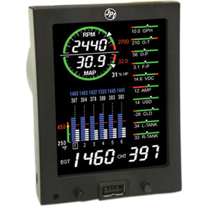
The EDM-960 Display Installation Before you install the EDM 960, located your fuel quantity calibration records as the installation engineer might need to refer to it at time of installation of the EDM 960. Also, before you install the EDM 960, it might be a good idea to spend a few minutes in the cockpit and decide on exact location of the EDM 960 display. The best recommendation is to install the display within the natural scan and easy reach of the pilot. When you have figured out the exact location where you want the EDM 960 placed, insert the special key card that came with the unit. Each unit is paired with a specific key card that has been pre-fed with data specific to your aircraft make and type. EDM-960 Key Card Installation Once the key card is inserted into the special slot in the unit, leave it in place and do not remove the card. When the aircraft engine is switched on, the Remote Auxiliary Display (RAD) of your EDM unit, will display the aircraft make and model in the right engine RAD. The Left side will simply display “EDM-960”. To install the key card, open the small access flap located on the side of the EDM-960 display. Hold the Key Card so that the UP arrow is facing up and insertion arrow is facing to the right. Now insert the Key Card in the guide rails until you feel it snap into place. Close the access flap. Power up the EDM and confirm that your aircraft make and model is displayed in the RAD. Install the EDM back into the aircraft. Power Connection: The EDM-960 accommodates 14V or 28-volt electrical system. When installing the EDM 960, care must be taken to ensure that the master bus power must be individually provided via three, 5-Amp circuit breakers, to the two DAU units and the EDM-960 head. The DAU ground wires should be connected to the engine block. The EDM 960 Twin is comes with Teflon insulated wiring harness configured for the correct number of cylinders for your aircraft. Each wire harness is marked C1= CHT-1, E1= EGT-1 and so forth. Post-Installation Trouble Shooting / maintenance: 1. On start-up, a missing column of figures in the display would indicate that the continuity check diagnostic routine has found an open line or probe with no connection. An error message will indicate which cylinder to look at. 2. A missing column of figures during flight indicates a reading that is jumping around or incorrect. Solution: Remove the probe from the line up to prevent false alarms. 3. A negative reading (-) in front of the number indicates reverse polarity on the red/yellow wire to probe. 4. Erroneous or erratic readings on one cylinder reading. Solution: Swap the suspected probe with a probe from a good cylinder. If the problem is transferred to the good cylinder then the probe is faulty and should be replaced. If the problem remains the same, it is in the Thermocouple hook-up wiring from the TIT Probe to the instrument or it can be in the ring terminals crimped to the wire. 5. If the temperature reading is changing more than 500°F in one second a loose wire crimp or probe could be the problem. A malfunctioning probe will automatically be removed from the scan. For more information, please visit: https://www.jpinstruments.com/shop/edm-960/  Even small quantities of dust and dirt entering data ports of various aircraft instruments are often sufficient to throw a fit at the most inopportune time. When receiving a newly purchased aircraft instrument, have it thoroughly examined and as far as possible, fully tested before installation and take off.
The installation process itself should be handled with care. Tighten the nuts (or screws) too much and you could end up destroying the outer casing which in turn could severely damage the internal parts. Aircraft instrument repairs are supposed to be handled by approved shop and done under controlled conditions. Every repair shop says so in the brochure. But the reality is usually something else. While these shops are run by properly licensed mechanics and engineers, they in turn, hire assistants who have little or no experience handling delicate aircraft instruments. Often times, damage can occur during a maintenance schedule itself. Surprised? Consider this; an inattentive mechanic’s assistant who drops an instrument just 6 inches, will subject its internal components to almost 2 G’s of force! This is enough to damage a lot of sensitive instruments especially Gyros. Similarly, careless assistants can result in contaminates or even tiny nuts and screws getting into the internal mechanism of an Aircraft Digital Instruments – imagine what that could do when the plane is being tossed around during a turbulence. It’s a headache you don’t want. Tips to maintaining aircraft instruments: 1. Do not lubricate fittings on vacuum gyros as it could result in over- tightening of screws and damage the fitting and the back-plate ports. 2. Cover / tape all ports when shipping to reduce possibility of dirt or dust entering the ports. 3. Gyros should always be allowed to run-down before removing. This is done to prevent damage to the gimbals and ultra-sensitive bearings. Similarly if you need to keep a gyro in storage for more than a month or two, it needs to be "powered-up" and operated for no less than 39 minutes so as to allow the bearings to be adequately lubricated. 4. If you need to check the accuracy of the Manifold Pressure Indicator, you should ideally compare it with the Altimeter's baro setting. Also remember, that some altimeters have vibrators in them. These vibrators are installed to reduce friction within in the instrument and thereby enhance accuracy. During maintenance, the mechanic needs to ensure that the vibrator is functioning properly. 5. Whenever the True Airspeed Indicator is taken out for maintenance, the mechanic needs to make sure the capillary tube is intact otherwise; the true airspeed indicator will have to be replaced. 6. It is very important that any instrument like Aircraft Engine Monitor should be properly tagged before handing over for repairs. 7. Always make sure the connectors on your fuel probes or Oil Temp Probes are clean and shiny. For more information on Aircraft Instruments, please visit: https://www.jpinstruments.com/ |
AuthorJ.P.Instruments was founded in 1986 in Huntington Beach, California, USA. Its founder, Joseph Polizzotto, is now the current CEO. Archives
May 2019
Categories
|

 RSS Feed
